
When installing lightning protection systems on telecommunications towers, three main considerations must be taken into account.
- Method of removing load from the mast after a lightning strike
- A method of discharging the charge induced in the mast structure as a result of the potential difference between the top of the structure and its base
- A method of dispersing charge in the ground
In our opinion, the best and most cost-effective way to dissipate an electrical charge is through the structure of the mast or lattice tower itself. AluPro products are equipped with a special lug in the lowest segment, which allows the entire structure to be connected to the building’s lightning protection system. For painted structures, be sure to remove the paint coating from the flanges of the segments to maintain electrical conductivity between them.
An alternative solution is to run an 8 mm diameter lightning rod to the top of the structure, which is then connected to a lightning spike (standard equipment on all AluPro masts). In our opinion, the lightning rod clamps should be insulated from the truss in this configuration; however, in practice, it is common to see metal fasteners attached directly to the mast.
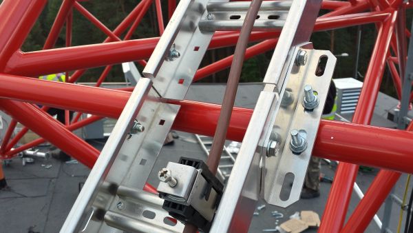
Radio operators often require the installation of a grounding cable (usually LY50), whose purpose is to equalize, at regular intervals (every few meters), the potentials induced on the feeder cable to the level of the lattice potential at the same height. A branch of the grounding cable is secured with a loop around the segment flange bolt. The photo above shows how the LY50 cable is routed through the AluPro cable ladder.
Ładunek do gruntu odprowadza się zasadniczo dwiema technikami. Pierwsza to tzw. „bednarka” – stalowy, ocynkowany płaskownik (przeważnie 30×4 mm) układany w wykopie o głębokości ok. 1,5 m. Gdy wykonanie wykopu ciągłego jest niemożliwe (kostka brukowa, nawierzchnia asfaltowa, mur), można zastosować pręty stalowe gwintowane na obu końcach, wbijane pionowo i łączone stalowymi mufami. Układ taki zwany jest potocznie „galmarem” od popularnej firmy produkującej to rozwiązanie. Pręty dostępne są w odcinkach 3-metrowych i skręca się je stosownie do potrzeb, zwykle po 3 sztuki, uzyskując łącznie ok. 9 m. Doświadczenie wskazuje, że w zależności od warunków gruntowych należy wbić od 3 do 18 galmarów, aby uzyskać normową rezystancję instalacji (maks. 10 Ω).
This technique is also used to supplement the perimeter lightning protection system installed with a metal strip. If the initial measurement indicates that the resistance is too high, we supplement the system with additional rods.
The following standards govern the proper installation of lightning protection systems:
- series of standards PN-EN 62305 (parts 1 – 4) Lightning protection,
- standard PN-IEC 60364–4–443:1999 Electrical installations in buildings – Protection against overvoltages – Protection against atmospheric or switching overvoltages,
- series of standards PN-EN 62561 (parts 1-7) Elements of a lightning protection device (LPSC),
- Act on Standardization, of 12 September 2002,
- and the Regulation of the Minister of Infrastructure on "Technical conditions to be met by buildings and their location" as amended.
You can explore this topic further by reading the article by Mr. Andrzej Sowa of the Białystok University of Technology.
Lightning protection in the construction industry